Canalblog
Suivre ce blog Administration + Créer mon blog

Reinvented Affordable Keyboard

2 novembre 2007

Fabrication of a pressure sensor

To build a Pressure Sensor, you need:

-one piece of conductive paper
-two pieces of metal aluminum or other metallic foil or copper adhesive
-one piece of non conductive material of the size of the conductive paper (optional)
-some plastic wrappers to wrap the whole and protect it.
-wires and soldering tools

Conductive paper can be found in graphic Arts shops. Take a multimeter with you and test the various papers that have a metallic color and also black or gray. Indeed, you will be looking for papers that are loaded with conductive pigments such as metallic ones, graphite or carbon black. If the ohmmeter indicates a variation of resistance when you place the electrodes on the paper then the paper is conductive. The picture below show an example of conductive paper.
Example_of_conductive_paper

Conductive metals are easy to find. You can simply use aluminum foil or you can buy some more expensive copper tape developed for shielding applications. This can be found at: http://products3.3m.com/catalog/us/en001/graphicarts/scotchprint/node_W46NXCHRZ7be/root_GST1T4S9TCgv/vroot_K9JT0N94GJge/gvel_RS1JV5NKF0gl/theme_us_scotchprint_3_0/command_AbcPageHandler/output_html
Here is a picture of some copper tape:
Copper_tape

The non-conductive material can be a piece of cardboard. You will cut it so that it makes a SPACER between the conductive paper and the metallic foil, and enables the contact of the conductive paper and the metal in its middle, such as the figure below. As there are two sides you can make two spacers. This is optional but it will enable to optimize the range of pressure and so the range of resistance variation. This will be infinite when no pressure is applied, whereas without a spacer you will loose some range.
Spacer2

Fabrication

The idea is to sandwich the conductive paper into two metal electrodes. To obtain optimal results,i.e. optimal range and repeatability of the response wherever you press on the sensor,  the zone of actuation is defined by the size of the metal electrodes. If the sensor is small this will not be a problem as it will not cost a lot of metal.

If the sensor is big, say more than 20 square centimeters, this will imply to use a lot of metal. Aluminum foil is then a good alternative but you must pay attention when converting it in order not to break the conductive flow. We recommend then using a heavy duty foil with higher thickness to prevent it from breaking. However you must notice that the conductivity of aluminum is not optimal as this metal oxidizes in its surface. Also, you cannot solder on aluminum and so you will have to add some copper tape on one side of the foil to solder the wire.

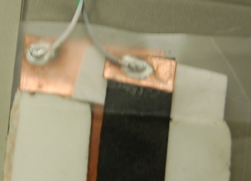
Then sandwich the paper into the spacers, making sure that the paper is smaller than the spacers. Add the metal foils (electrodes) on each side and connect them to a wire. You may want to extend one side of each electrodes in order to solder the wire far from the actuation zone as shown in the figure below (here the sensor is mounted without spacer, and the metal electrodes are extended on their opposite end. One end is soldered to a wire).

Connection_for_pressure_sensor

Last, wrap the whole with a plastic wrapper to protect the sensor as done in the figure before. This will solidify the sensor and protect it from moisture and temperature variations as well as from your maniulation of it.

Connections:

You can then obtain a pressure sensor ready to use, you just have to add a resistor (R1) to one of the wires for a voltage divider, the choice of the resistor depending of course on the resistance of the paper band. The idea is to maximise the range of a value Vout=Vin*Rpaper/(R1+Rpaper). For instance if the resistance of the paper ranges from 100 Ohms for high pressure to 6kOhms for very light pressure, using a resistor R1=800 ohms will provide the widest range for Vout.

section_of_a_paper_pressure_sensor

For the connection to a Digital to analog Converter, the wire connected without the resistance is the ground, then the wire with the resistance is Vout and the resistance that connects to the same wire goes to Vin.

Note:

If you do not have copper foil, you cannot solder the wire. A solution is to use a stapler. This works well but make fragile connection, so take care for wrapping the connection to solidify it.

Publicité
Publicité
1 novembre 2007

Fabrication of a position sensors

To build a Position Sensor, you need:

-one band of conductive paper
-one band of metal aluminum or copper adhesive of the length of the conductive paper and the same width.
-one piece of non conductive material of the length of the conductive paper and larger than it.
-some plastic wrappers to wrap the whole and protect it.
-wires and soldering tools

Conductive paper can be found in graphic Arts shops. Take a multimeter with you and test the various papers that have a metallic color and also black or gray. Indeed, you will be looking for papers that are loaded with conductive pigments such as metallic ones, graphite or carbon black. If the ohmmeter indicates a variation of resistance when you place the electrodes on the paper then the paper is conductive. The picture below show an example of conductive paper.
Example_of_conductive_paper

Conductive metals are easy to find. You can simply use aluminum foil or you can buy some more expensive copper tape developed for shielding applications. This can be found at: http://products3.3m.com/catalog/us/en001/graphicarts/scotchprint/node_W46NXCHRZ7be/root_GST1T4S9TCgv/vroot_K9JT0N94GJge/gvel_RS1JV5NKF0gl/theme_us_scotchprint_3_0/command_AbcPageHandler/output_html
Here is a picture of some copper tape:
Copper_tape

The non-conductive material can be a piece of cardboard. You will cut it so that it makes a spacer between the conductive paper and the metallic foil, and enables the contact of the conductive paper and the metal in its middle, such as the figure below.
Spacer2

You then have to place the copper tape is one side of the spacer and the conductive paper in the other side of the paper. An example is shown for the paper facing the spacer.
Spacer_and_conductive_paper

Wrap the whole, except for the end as you will have to create connections to electrical wires.

Connections:

Two designs are possible when building the position sensor. One uses two connectors and a resistance for a voltage divider. Connect one end of the paper to a wire and the same for the metallic band as shown in the figure below:
Connections

You can then obtain a position sensor ready to use, you just have to add a resistor (R1) for a voltage divider, the choice of the resistor depending of course on the resistance of the paper band. The idea is to maximise the range of a value Vout=Vin*Rpaper/(R1+Rpaper). For instance if the resistance of the paper ranges from 100 Ohms to 6kOhms, using a resistor R1=800 ohms will provide the widest range for Vout.
For the connection, the wire connected to the metal plate is the ground, then the wire connected to paper is Vout and the resistance connects to the same wire and then goes to Vin.
If you do not have copper foil, you cannot solder the wire. A solution is to use a stapler. This works well but make fragile connection, so take care for wrapping the connection to solidify it.

Another technique consists in making a wiper as known in electronics. The idea is to use the paper as both resistances of the voltage divider. The advantages are that the response will be linear, which was not the case before and that the output will be used for the full range. The drawback is that you have to connect the other end of the paper as shown in the figure below.
Drawing_of_a_position_sensor

Here A1 is the ground, A2 is Vin and A3 is Vout. Enjoy...

18 août 2007

Un exemple: augmenter sa guitare électrique

Structure / capteurs :
La guitare augmentée que nous avons réalisé, a été developpé sur une base de capteurs en papiers transmettant un signal de position pour certains, de pression pour d’autres. Ces capteurs ont été placés sur une guitare éléctrique dont le signal audio transite par un ordinateur, ce dernier servira dans le même temps à convertir les informations recueillies par les capteurs et transmises à l’ordinateur via une manette de jeu (joypad) connectée en usb. Le son une fois modulé est renvoyé dans un amplificateur, comme une guitare éléctrique standard.  Afin de répondre à des prérogatives ergonomiques et de confort de jeu, nous avons opté pour un capteur de position en ” U” , (voir figure 1), agrémenté d’un capteur de pression  situés au dessus des micros de la guitare. Ceci permettant de controller les effets tout en jouant et  sans lacher le  plectre.

àGuitare_gros_plancapteur_en_U

De plus, nous avons avons placé un capteur de pression sous la plaque de protection de la guitare située en dessous des micros.  Enfin, le joypad a été installé après le chevalet en bout de guitare. 

Guitare_vue_de_dessus_4

Une fois réalisé, nous avons obtenu une guitare augmentée de deux capteurs de pression, d’un capteur de position et des capteurs du joypad. 

Utilisation / Mapping : 
Dans le cas de la guitare augmentée, l’idée était d’employer des capteurs pour controller des effets appliqués au signal audio, et d’autres pour lancer des sons choisis et stockés dans l’ordinateur (sampling).

- Les capteurs de position et de pression  ont été dédiés au contrôle des effets, prenons l’exemple d’un effet  “delay” :  dans ce cas le capteur de pression peut permettre un reglage du tempo du delay (tap tempo). Concretement cela permet d’ajuster le tempo du delay au tempo du morceau que l’on est entrain de jouer  simplement en battant la mesure avec le plectre ou le doigt sur le capteur pression. Le capteur de position, quant à lui, peut permettre un reglage fin de la durée du delay (temps), de son volume ou de n’importe quel autre paramètre du delay. Dans le cas d’un effet “tremolo”, le capteur de pression pourra fonctionner comme un interrupteur on/off de l’effet, et le capteur de position reglera la vitesse du “tremolo”, ou d’un autre parametre de l’effet choisi.  L’intérêt du capteur de position dans le contrôle des paramètres d’un traitement audio par un effet est immense, car il permet  un controle des paramètres sur une large échelle de valeurs, assignable à notre guise. Les possibilités n’étant limitées que par notre imagination.

- Le capteur de pression situé sous la plaque de protection a été dédié au lancement d’échantillons audio sélectionnés et stockés dans l’ordinateur. Le son choisi est lancé par simple pression sur la plaque de protection de la guitare. Ce capteur a été couplé au joypad afin de permettre une incrémentation dans la liste des sons choisis, ainsi en manipulant le joypad on choisit le son désiré et on le déclenche en appuyant sur la plaque de protection au moment souhaité. Ici, ce système permet de déclencher un son d’orage, un bruit de porte, une texture sonore, ou n’importe quelle source audio à partir de la guitare directement: là encore, les possibilités sont infinies...  Bien entendu, toutes les modifications réalisées sur cette guitare éléctrique n’enlèvent rien de ses qualités acoustiques ou de l’intégrité de sa lutherie: le système étant adaptable à n’importe quel autre instrument. 

L’instrument obtenu, la guitare augmentée, est unique de part;
- la flexibilité de son utilisation liée au nombre de combinaisons possibles entre les différents capteurs et le  choix des paramètres modulés
- l’appréhension même de cet instrument , c’est à dire dans la manière que l’on peut avoir d’en jouer, et  ainsi envisager la création sous d’autres lumières une fois l’instrument paramétré selon ses propres souhaits - sa modularité, qualité principalement dûe à la facilité de fabrication des capteurs en papier permettant l’extension des possibilités selon les inspirations ou les exigences du musicien.

Publicité
Publicité
Reinvented Affordable Keyboard
Publicité
Publicité